Le tolleranze attirano tutta l'attenzione su un disegno. I dati decidono se tali tolleranze possono essere mantenute.
Cosa fa effettivamente un dato
Un dato indica all'operatore e all'ispettore da quale superficie viene misurato tutto il resto. È il riferimento rispetto al quale la parte viene costruita e giudicata.
Se un disegno non ha riferimenti, o li ha sparsi senza uno schema chiaro, il fornitore ne sceglie uno proprio. Questa scelta influisce sul modo in cui la parte viene fissata, il che influisce su dove si accumulano gli errori. Due fornitori che realizzano lo stesso disegno con le stesse tolleranze possono produrre parti che superano l'ispezione e tuttavia non si scambiano nell'assemblaggio.
Scegliere i riferimenti dall'assieme, non dal modello
La regola più affidabile che conosciamo: il riferimento dovrebbe essere la superficie che posiziona la parte nel suo assemblaggio reale.
Se una staffa è fissata a una piastra sulla sua faccia posteriore piatta ed è posizionata tramite due fori di riferimento, quella faccia e quei due fori costituiscono lo schema di Riferimento. Il dimensionamento da un'origine del modello conveniente è invece il punto in cui iniziano i problemi di intercambiabilità.
Sembra ovvio. In pratica, gran parte dei disegni che riceviamo sono quotati in base a qualunque sia l'origine CAD.
Le conseguenze sui costi
Fissaggio. Uno schema di dati sensato consente di trattenere la parte una volta, sulle superfici che contano. Uno scadente impone operazioni aggiuntive per raggiungere caratteristiche riferite a volti diversi.
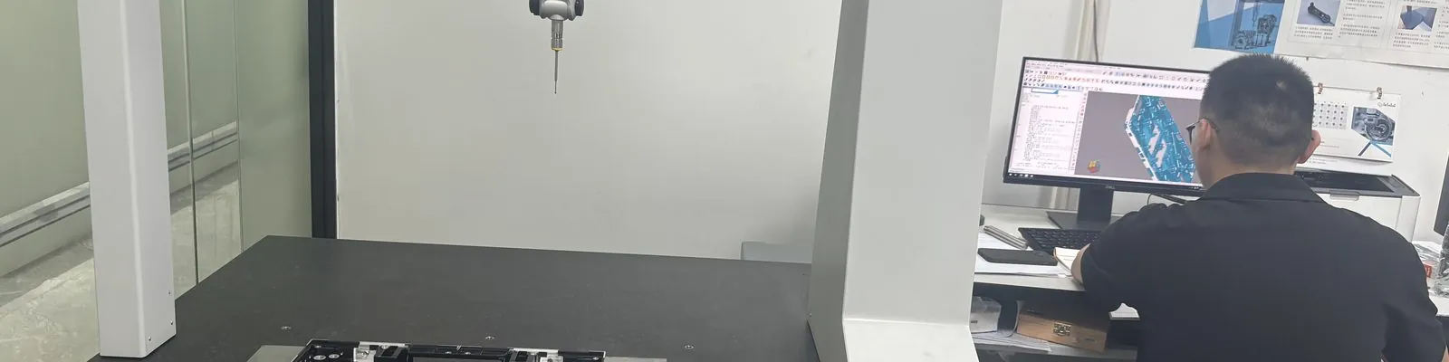
Ispezione. Le caratteristiche riferite ad un dato chiaro possono essere misurate in uno CMM impostazione. Le funzionalità a cui si fa riferimento in modo incoerente necessitano di un riposizionamento e ogni riposizionamento aggiunge incertezza e tempo di misurazione, il che risulta nel prezzo unitario di qualsiasi parte con un requisito di ispezione completa.
Argomento al primo articolo. Quando una dimensione è fuori uso e il disegno è ambiguo riguardo al punto da cui è stata misurata, nessuno può risolverlo. Questa è la causa più comune delle controversie sul primo articolo che vediamo.
Lo schema a tre piani
Per le parti prismatiche l'approccio standard prevede tre riferimenti reciprocamente perpendicolari: primario (solitamente il piano più grande, controlla due rotazioni e una traslazione), secondario (controlla una rotazione e una traslazione), terziario (controlla l'ultima traslazione).
Per le parti rotonde, un asse e una faccia. Per una parte posizionata sui tasselli, la faccia più i due fori come modello.
Non è necessario essere uno specialista GD&T per farlo bene. Devi rispondere a una domanda: cosa tocca questa parte quando viene installata e in quale ordine si posiziona?
Cosa controllare prima di inviare un disegno
- Ogni caratteristica critica fa riferimento a un dato e non a un'altra caratteristica?
- I riferimenti sono le superfici su cui si trova effettivamente la parte?
- I datum possono essere toccati fisicamente da una sonda di ispezione? Un dato su una superficie che successivamente viene coperta o rimossa non può essere verificato.
- La sequenza dei dati è indicata in modo che primario/secondario/terziario non sia ambiguo?
La versione breve
Specificare i dati non costa nulla ed è costoso sbagliarli. Sceglili dall'assemblaggio, stabilisci la sequenza e assicurati che possano essere misurati. Sono i cinque minuti con il massimo effetto che puoi dedicare a un disegno di lavorazione.